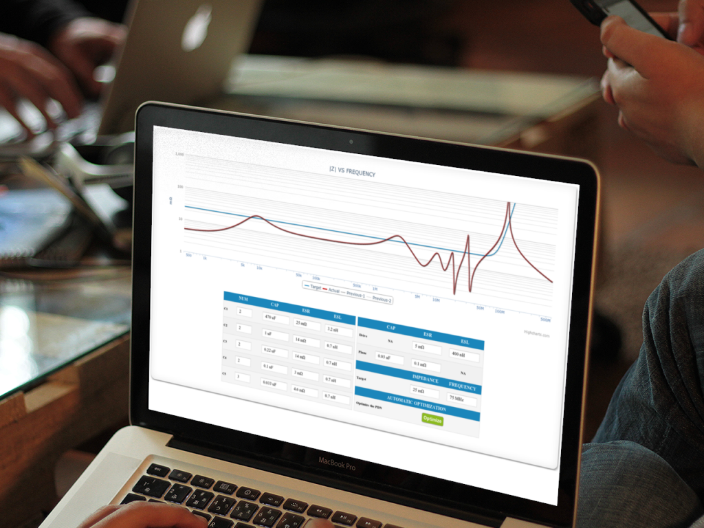
An automatic PDN optimizer? For free? Yes – find the right number and types of decoupling/bypass capacitors quickly. This is exactly what this new free web tool does right in your browser. No install. No download. And you get to try it out first… (almost)…
Figuring out how to design a solid bypass and power distribution scheme for (digital) circuits has always been fairly simple – if you knew how to do it. And there have been spreadsheets floating around the internet to help you do that for ages.
But now it’s automated one more step: With a one-click optimizer button…

Well, really it’s a 3-step process:
- Define the capacitors you want to use. You need to know the ESR and ESL also, but there is help available in the tool to learn how to find or measure those values.
- Define the target – how low an impedance you need. And to what frequency (You do not need low impedance all the way to infinity).
- Hit the Optimize button and you are done.
It is as simple as that.
And the benefits you get from having solid power supply bypassing are significant in my experience. Actual examples include: Pass EMI tests, parts actually operating within supply voltage specs, better jitter performance, eliminated rare “mysterious” hang-ups, higher operating frequency for memory, etc.
So give it a try – I really would love to hear your comments, ideas, and suggestions for making this PDN optimizer as useful as possible for you.
Don’t forget to give some feedback – on why you can’t use it… or why you love it… or what improvement you would like to see…
 M.Sc.EE, SI Consultant
Nice tool. Find the entry of R and L behaves a bit unexpected – until you realize that it takes mOhm and nH as the unit. I.e. have the unit in the header line instead of in the cell. This would make that clear.
It could be an idea to give the option to enter C,R and F_resonance in stead. The latter is more often specified than the inductance.
Thanks. And we will look into the display bug. You ideas for improvement have been added to our list. Great ideas.
You may not want to use resonance frequency from a capacitor datasheet as the input parameter as that is usually a very optimistic value not taking the real mounting inductance (fully) into consideration.
Ok, That is a point. So you actually want to have two inductance values in the setup: an L_capa_resonance based on the datasheet’s resonance frequency and added to that an L_board. I.e. just an extra collumn in your table. If user does not know what to put for L_Board, then put 0, but the resonance based inductance stays as a minimum value only changable via the resonance frequency. (which user could overrule by putting F_resonance= Large)
* The way the tool retains the last simulations is brilliant.
* Setting C=0 removes this type from the simulation is great.
* [?] pop-up could quote the unit: Capacitance [uF]
* Autoscaling of the y-axis would be nice – to see how bad combination really is.
* There is room for a bit of circuit diagram to support the meaning of the various values: Example is seen here (about page 2) = https://www.intel.com/content/www/us/en/programmable/documentation/jba1434040249865.html