A short video to demonstrate crosstalk and try to explain how that works in the stripline environment. We look at both the near-end and far-end crosstalk and also explain why that depends on the termination used.
In a real digital circuit, we will have one of these termination situations:
- Open/high impedance (typical CMOS input impedance)
- About 10-15 ohm termination (the typical output impedance of a driver)
- Matched (typically 50 ohms) termination
In the video, we look at open and matched – you will have to interpolate for the middle case 🙂
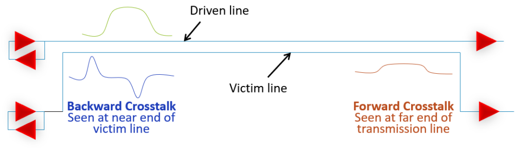
Crosstalk is a very important topic in signal integrity – this is the key parameter defining trace-to-trace spacing for layout. We looked at this earlier using S-parameters and just how well the simulations and measurements match.
Let me know what the next crosstalk video should look at? Maybe crosstalk for microstrip? Maybe the effect of guard traces? Or?
 M.Sc.EE, SI Consultant
Leave a Reply