A long time ago I did a series of posts about Altium for signal integrity (part I, part II, part III). That did not go well for Altium. Ever since then, I have been on the lookout for a free or cheaper alternative to the kings of the mountain of signal integrity simulation: Hyperlynx and (maybe lesser known) SigXplorer for doing simulations with IBIS models. This is still a question I get asked a lot.
Recently KiCAD 8 came out. KiCAD has been an amazingly capable free open-source EDA package since version 6. With schematic entry and PCB layout tools – and a nice flow to work as a front-end for various Spice-style simulators. With great sponsors, it has real traction and is getting to a level where I would say it is a serious contender to commercial tools for things that are not too exotic.
Now it is time to rerun the same IBIS simulations on KiCAD 8 as a front-end to ngspice (with an IBIS-to-Spice converter in between). The first test is a simple analysis of one 74ALVC244 (datasheet) output driving one of the inputs. All operating off a 3.3V supply.
Drawing the circuit
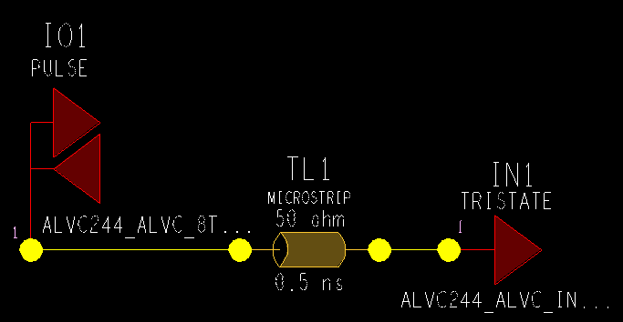
Cadence calls their tool SigXplorer in OrCAD PCB SI (we were on version 16.5 here). The sketch for the analysis is set up like this with the I/O driving a pulse into a transmission line (ideal 0.5ns, 50R) to the input.
In KiCAD this exact same simulation can look like this.

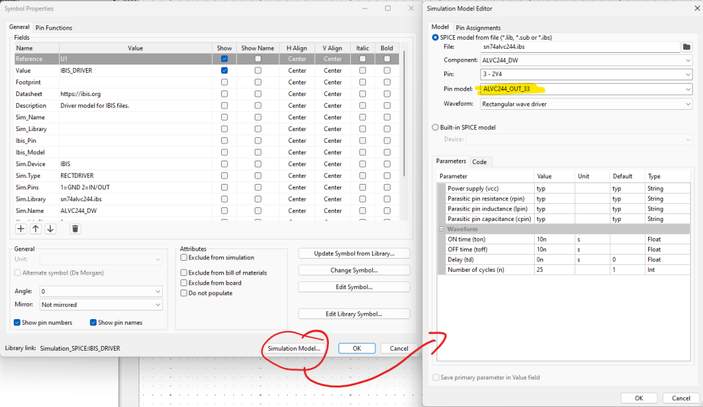
Models from the IBIS file are loaded and attached under the schematic symbol like this for the driver. Similar for the receiver/input models.

Weirdly enough you also set many of the simulation parameters in the driver symbol, so you will find yourself opening the symbol many times to change the simulations you run on the circuit.

Some of these are a little confusing when you come from other IBIS simulators.
“Power supply (vcc)” can be set typ/min/max and has no effect. This is not a setting you normally see in IBIS simulators. Or maybe this is supposed to switch between TYP/SLOW/FAST models? Unclear for me – let me know if you have info about this.
“Parasitic pin resistance/inductance/capacitance” can also be set typ/min/max. This is a bit strange. The typical IBIS models have two places where you can get R/L/C pin parasitics from. The [Package] section lists typ/min/max (with typ = average) for the entire package and the [Pin] section overrules this with more accurate values for the individual pins.

Being able to select typ/min/max is not that important in practical cases for this reason.
For the “rectangular wave” stimulus you also select t(on), t(off), Delay, and number of cycles to simulate. This seems okay although it is still a bit weird to do this as part of the symbol when the simulation time is set up in another window.
Simulation results
Running the simulation is fairly easy. You press the “simulation” button in the toolbar.

First, you get a ton of warnings and other “output” that may or may not matter – not much different from other simulators and other tools. Then you get a new window and can press a button for “Edit Analysis Tab”, which brings up the window where you set the simulation time and step size.

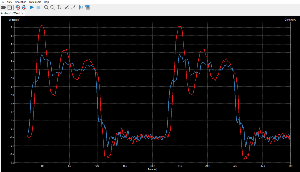
This is what you get when pressing “play”:

The red curve is the input being driven (so the output of the transmission line). The signal we are interested in.
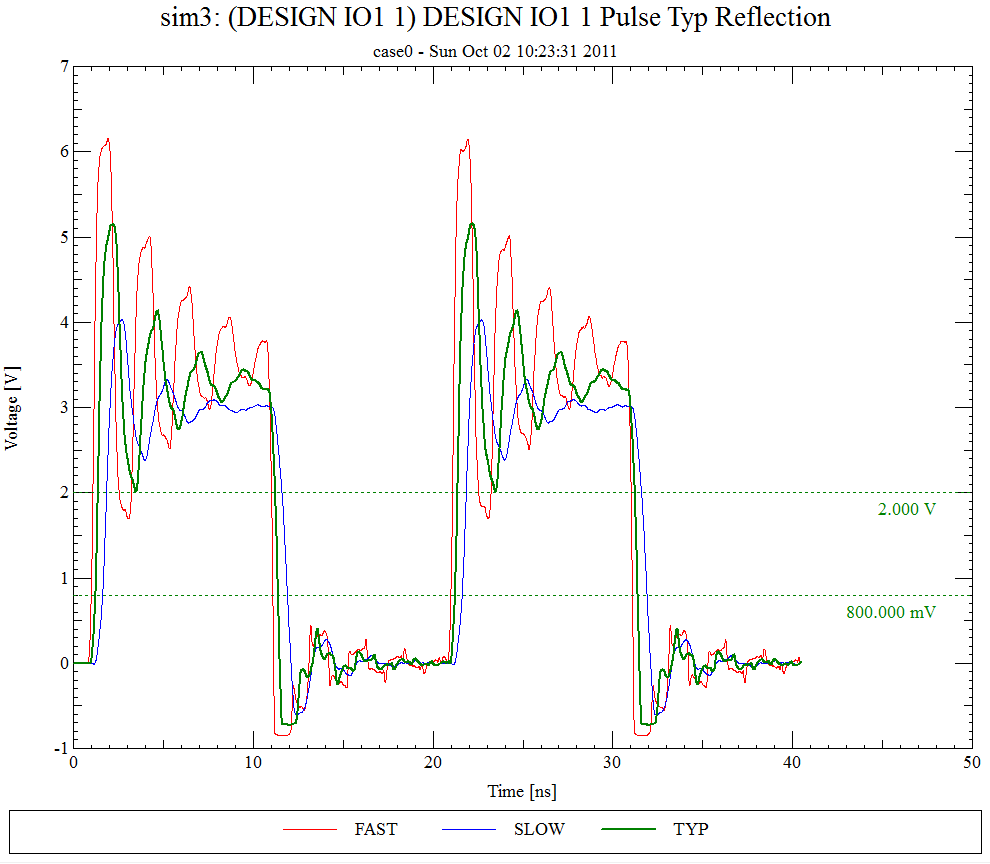
Compare this to the results from the Cadence SigXplorer simulation, where we should be looking at the green curve which is for the typical case.
The results are pretty close which is really nice. This is the first time I have seen a free/cheap tool do this with a reasonable easy-to-use user interface.
It’s pretty obvious that the input diode is clipping the waveform in the low state in the Cadence simulation. The ngspice simulation does not really show that as clearly – maybe that is okay but it is a bit concerning. Would be good to understand.
Conclusion
For a simple analysis like this, KiCAD/ngspice and the IBIS-to-Spice converter are doing an amazing job given it is all free and open-source. I am very impressed and looking forward to following the development of this simulator/front-end combination.
A few things I would like to see improved/understand better:
- Being able (or figuring out how) to do the simulation for the SLOW/FAST corners also. The models in the IBIS file list both the typical and the fast/max and slow/min corners, so it is really just a question of getting the IBIS-to-Spice converter to pick the right columns in the model.
- Power-aware simulations where the supply voltage at the die level comes after the R/L/C parasitics listed for the power pins.
- Easy way to setup a sweep – like the SLOW/FAST/TYP sweep I ran in the Cadence simulator as shown in the plot above.
- And as a nice-to-have: Collecting all the simulation setup in one dialog instead of putting some of it under the driver symbol and some in a simulation setup window.
I am sure there will be more as I explore what else the simulator can do (and not do). And it is very likely that this is all already there and I just don’t understand how to do it 🙂


 M.Sc.EE, SI Consultant
Leave a Reply