In part I of this series of comparisons I started my quest to figure out if Altium is any good for SI analysis. It’s clearly one of the cheapest tools out there that allows you to do IBIS model-based simulations. Forgetting the price, can it get the job done?
Last time I did a very simple reflection analysis of one 74ALVC244 (tri-statable) output driving an input of the same type device. Now it’s maybe time to look at the results and see if we really need termination resistors for this.
Let’s repeat the input voltage waveform from the simulator. Here showing the results from Cadence, but the Altium curves were very similar.
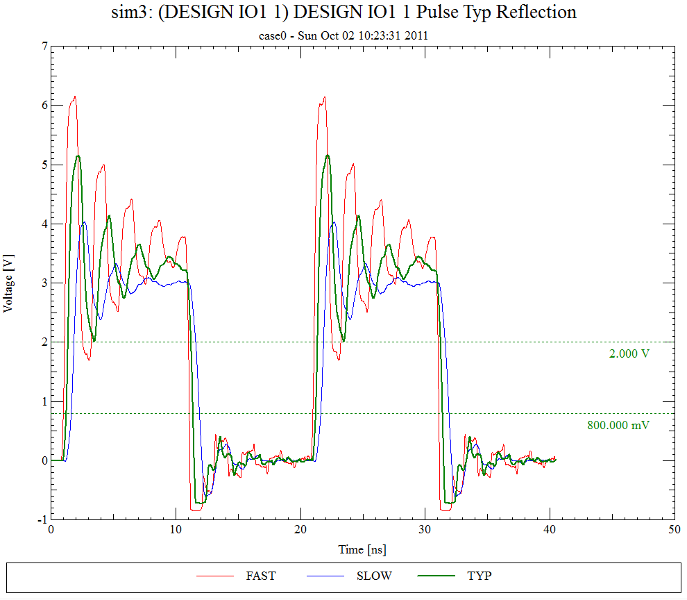 Looking at the waveform it becomes clear that a termination resistor could make this look a lot nicer. But is it really needed? Let’s look at the datasheet.
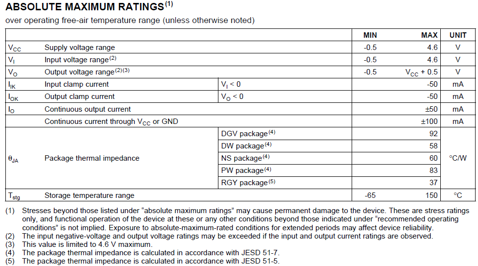 The Vi input voltage range is -0.5V to 4.6V. Looking at the simulated curve that seems to be exceeded a bit in the low end with the input voltage going down to -0.7V with the input diode clearly clamping. But look at the note (2) allowing this, provided the clamp current is within the listed limits. So in order to asses this we should really be simulating the current flowing into the input.
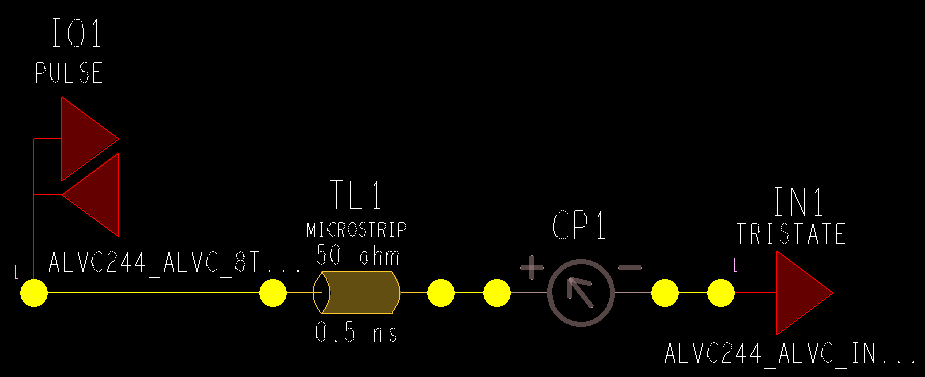
This is easy to do with Cadence SigExplorer – look:
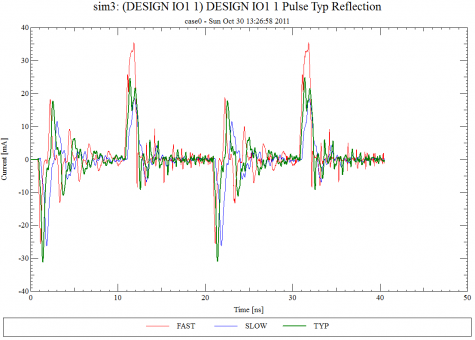
 And the results showing the input currents assure us that the allowed 50mA is not exceeded:
How can we do this in Altium? Honestly, I have no clue how or if this is possible. Do you have any idea how to do this? Please let me know.
Now, this was a lot of work on the low state – how about the high state?
The upper input voltage limit from the absolute maximum rating section of the datasheet of 4.6V also seems to be exceeded quite a bit for both the TYP and FAST corners. So right there I know that there is really no way around finding a good termination scheme.
Conclusion
Simulations to observe input current does not seem to be possible with Altium. For that, you need a better tool.
Watch this space as the story continues in part III.
PS: Note that I will be happy to continue my exploration of Altium SI features if someone will lend me a license for a while… ![]()
Q: How do you simulate the input current in Altium like shown for Cadence? Or is this completely irrelevant for you?
 M.Sc.EE, SI Consultant
Leave a Reply