A recent question on the Electrical Engineering Stack Exchange website, which is the closest we get to a hardware version of the hugely popular software engineering resource Stackoverflow, got me thinking of twisted pair cable termination and how bad things can really go.
The user Andy sent an 80 MBps signal through a 50-meter cable to a differential receiver and found the thing working only when he used one termination scheme (#2) and not the other (#1).
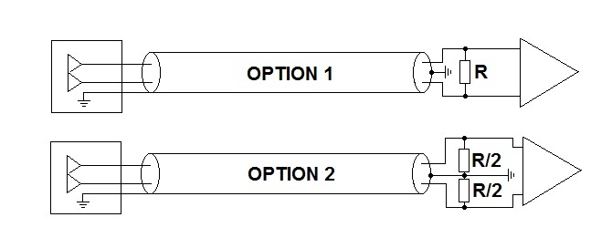
When you compare the two termination schemes with an ideal differential signal, they are identical from an AC point of view.
You may want to use a different termination voltage, use a cap or 3 resistors in order to center the received signal around the optimum working point for the receiver. But that is more of a DC consideration.
Common Mode
The interesting thing here is when you look at the two schemes with a common-mode signal. Meaning both signals of the pair are identical. In this case, termination #1 is very high impedance resulting in 100% reflection or voltage doubling at the receiver. Termination #2, on the other hand, has a termination for a common mode signal as well. This common-mode termination may or may not be perfectly matched depending on the specific cable used, but it’s much closer than in scheme #1.
Mode Conversion
So how come a perfectly symmetric output from the drivers suddenly have a significant common-mode component at the receiver?
This can happen in multiple ways, which we commonly refer to as ”differential to common mode conversion”.
In this case, you have a fairly long cable (50 meters) which means a number of things that affect the propagation delay in the cable may be very different between the two wires in a pair. This could be the physical length, average dielectric properties, etc. In addition to this, no drivers are perfectly symmetric and this does usually not get any better when mounted on a real board with differences in stray capacitance, etc.
Long story short: Some of the signal energy will arrive at the receiver as common mode energy. No matter what you do.
Simulation
But just how much of a problem is this? Let’s do a quick simulation to find out.
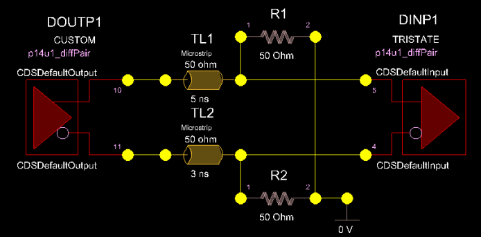
A differential driver with an 80 MBps signal is driving two ideal transmission lines with a 2ns difference in propagation delay is used for the simulation. The results show how much effect termination of the common-mode signal has.
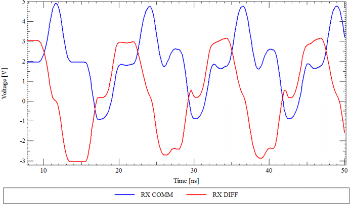
Termination scheme #1 (differential mode termination only). Notice how this seriously affects the differntial mode signal.
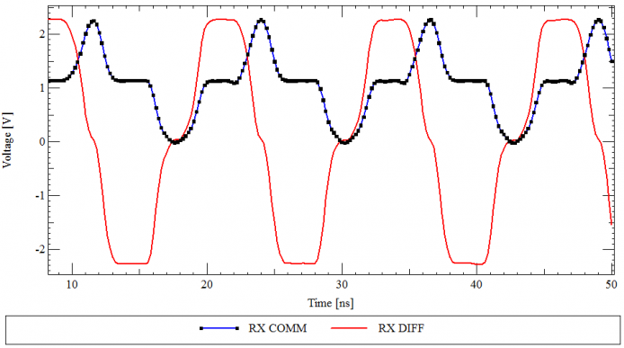
Termination scheme #2 (both common-mode and differential mode termination). Notice how the differential mode signal is still as nice as it can be given the massive skew.
As can be seen, the effects of not terminating the common-mode signal in the receiver end are quite visible on the signal quality. This would probably not be enough, in this case, to render a system unusable, but notice that we have not accounted for loss and other impairments in this idealized simulation setups.
There is a whole lot more to say about common mode and differential mode signals that we can get back to some other time. Just remember that common-mode signals on cables are a likely source for EMI problems as well.
Update
So why is scheme #1 often recommended in application notes for LVDS termination on a board? Well, if you compare the amount of skew the happens across a pair of traces on a PCB to the rise/fall time of the signals, you will see that the skew introduced is usually less than the duration of the edge. In that situation, the common-mode signal resulting from the mode conversion is much less severe.
Simulation setups
For completeness, here are the simulation setups used for the two twisted pair cable termination schemes.
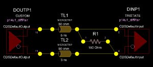
Simulation setup for termination scheme #1.
Simulation setup for termination scheme #2 (update: both resistors are 100R in the simulation shown).
 M.Sc.EE, SI Consultant
For scheme 1 the two resistors terminating the cable should be 50 ohm each not 25 ohm each – 25 ohms would imbalance the basic data received differentially
You are so right. Thanks for spotting the error. It’s corrected in the above post now – and as you can see, the difference is not that big. The conclusion still holds.
Strange. Using a 2 50 ohm TL rather than a 100 ohm diff TL. Does not make sense for LVDS. LVDS uses 100 ohm diff traces and cables.
Thanks
Muhammad,
As a model, two 50R transmission lines behaves the same as an ideal 100R differential transmission line 🙂
I came across a receiver that used your scheme #2 for a RS-422 setup. We are experiencing RS-422 transmitter failures with 60ohm to grounds. We try to isolate our grounds. Data is at 2Mb/s or less.
Why do the designer if the transceivers just show a termination like your Scheme #1?
Good question. Ask that to the designer – remember, not all designers are as smart as you are 🙂