A quick how-to for you: the PDN measurement video.
How do you do validate bypass capacitor selection and effectiveness on the mounted PC board?
This is very easy to do, and this video was created to illustrate how this is done in the lab with a Rohde & Schwarz network analyzer. It used to be a picture that was worth a thousand words, but these days it’s a video.
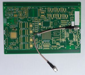
The two boards used in the video are actual designs, one mounted with capacitors only and one bare. For the purpose of demonstrations, both boards have been equipped with SMA connectors, so the measurements can be done easily with both hands-free.
Simpler methods for probing exists, and that may be a topic for another post. Usually probing it not a big issue, but obviously it’s easier when the boards have been prepared for probing.
In reality, the measurements work just as well on a board with all parts mounted, where you have the benefit of also measuring the capacitance on-chip and package.
Youtube PDN measurement video
(Also available directly on YouTube)
The frequency range used in this demonstration is 9 kHz to 1 GHz, with as low a measurement bandwidth as you can bear waiting for (lower bandwidth, longer sweep). A nice thing about this analyzer is that it can do a logarithmic sweep and display the results that way as well. This is exactly how we want to see the results.
When measuring the S21 insertion loss, this comes out in dB. As shown, this is converted to Ohms by the simple formula:

The boards used in the demo are pretty simple, but the method works for all types of boards. Here is another example, which was used for the test of how the PDN measurement changes when the measurement points are changed.
Was this useful? The focus here is on content rather than video/sound quality – is this the right trade-off? Please use the comment field below.
 M.Sc.EE, SI Consultant
Leave a Reply