Is there a risk of ground offset error when doing PDN measurements? This is another question that popped up after the story about what happens when the test points are moved in a network analyzer setup for measuring bypass (or PDN – Power Distribution Network) on a board is: Would it change anything if the coax into the network analyzer is run through a ferrite toroid (for common-mode rejection).
This is a good question, as the 4-point measurement setup does have an issue with the ground offset. Both the generator and the receiver shield/ground on the network analyzer connectors are very well connected together at the instrument. There is a non-zero impedance in the cable shield, so there will be a voltage difference between the two ends of the cable shields because of the 0dBm signal the generator is driving through the cable and into the ~0.01R impedance of the PDN. This voltage difference will be part of the measured signal.
Ideally, we would want a floating input, and the problem would go away. There are network analyzers with pseudo-floating inputs, but this is not a feature in the lower and more affordable instruments. Increasing the common-mode impedance in the receiver cable sounds like a good idea, so let’s try it.
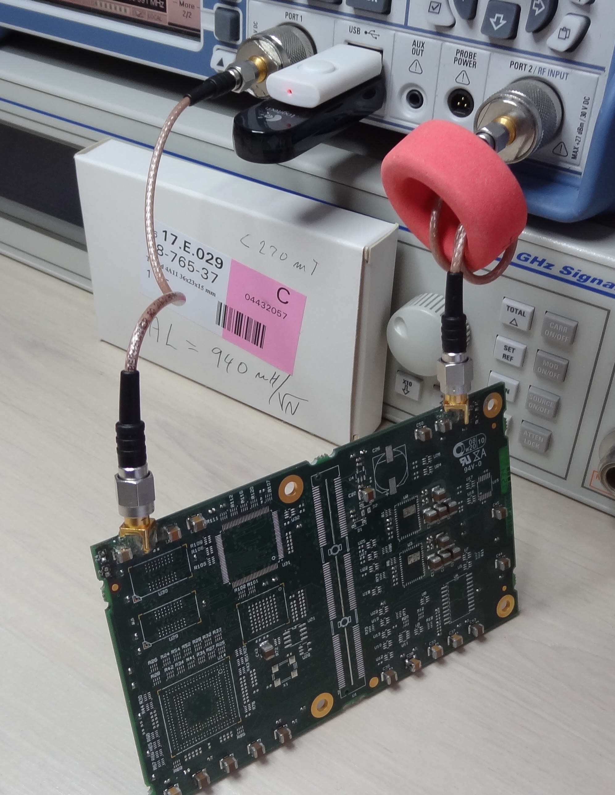 The board is populated with capacitors only (read more about what happens if you populate all parts in another post). The toroid is selected as the one that made the biggest difference after trying a box full of different ones. Here is the datasheet for this specific toroid.
Results
The impedance versus frequency was measured both with and without the ferrite toroid from 9kHz to 500MHz. This is how it looks on the analyzer screen:
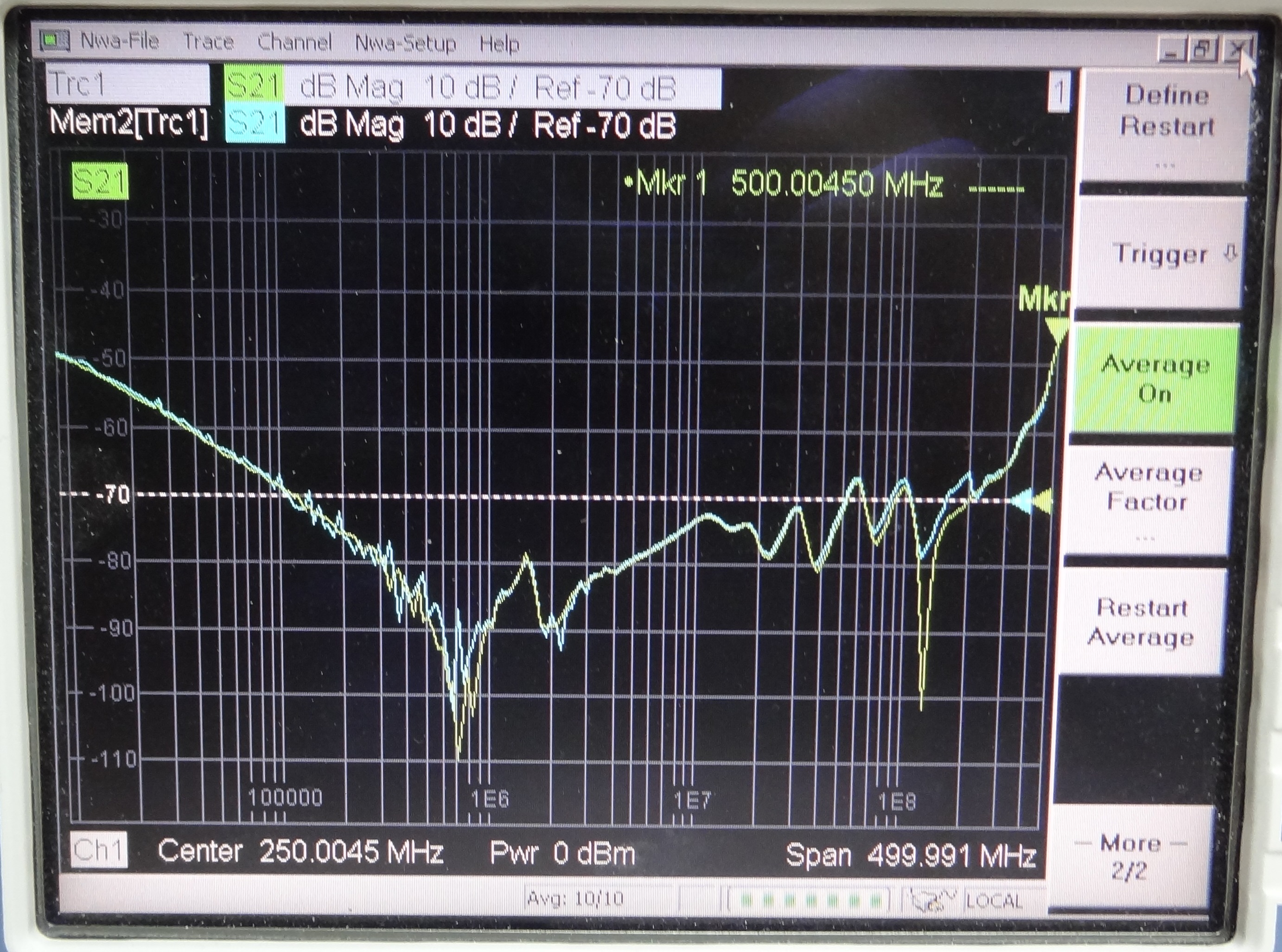 The yellow curve is with the toroid and the bluish curve is without. The differences at the lower frequencies are most likely due to noise, but the difference most visible between 100MHz and 200MHz is clearly related to the toroid.
Incidentally, the frequency at which we can see a significant difference is also around the frequencies where the impedance curve starts to be less interesting as it depends more on where exactly the test points are located (see the post about what happens when the test points are moved). In other words, the impedance is dominated by resonances – not the discrete bypass caps. So in practice, this is not a big deal.
Again, this was tried with a bunch of different ferries and this is the biggest difference seen.
To be sure that the measurement setup is sufficiently solid, a few other things were tried with very little impact:
- A much longer cable of the same type (for higher cable shield impedance)
- 20 turns on the toroid with the longer cable
- 1-100MHz RF 50R transformer to create a floating input
How to avoid PDN ground offset error in measurements has been analyzed in great detail by Istvan Novak in his paper “Accuracy Improvements of PDN Impedance Measurements in the Low to Middle-Frequency Range” presented at DesignCon some years back. You can read his manuscript and see the slides on his website. Highly recommended if you want a much more detailed story.
 M.Sc.EE, SI Consultant
Leave a Reply