In this quick video I will show how to do a simple impedance test trace TDR measurement on a PCB using a homemade probe and the LeCroy SPARQ.
This nice piece of equipment can do all kinds of fancy stuff including de-embedding of cables (which I used here) and gating away the effects of probes and launch (which I did not use here). Here I use it for a plain TDR measurement.
On outer layers a tolerance of +/-20% is not unreasonable for the impedance of your traces. This board is within about +/-10%, which is very fine. Obviously you should repeat this measurement across a number of boards. The other layers of the board are quite difficult to test, as the designer did not provide good ground reference connections for the test points.
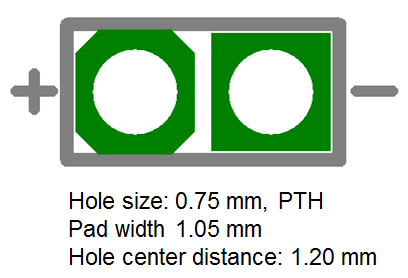
I recommend a simple test point like this, which fit nicely to the homemade probes I use.

You should easily be able to fit this into most boards. The test point itself is not much bigger than a 0603 part. The length of the test trace can be just a few cm or up to maybe 10cm.
 M.Sc.EE, SI Consultant
Leave a Reply